Magnetism
Magnets
Ferromagnetic metals such as alloys of iron, nickel, cobalt and gadolinium have a North and South pole. Whereby the each metal is composted of magnetic domains that cause the metal (no matter how small to always have a north and south pole). Common non-ferromagnetic metals include copper and aluminum. If allowed to freely rotate, magnets will align themselves in a north-south direction - or the North pole of the magnet is attracted to the magnetic South pole
The law of magnetic poles: Opposite poles attract each other and similar poles repel each other.
Magnetic Fields
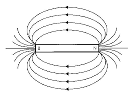
The force that magnets exert across distances in space is their magnetic field. It can be detected by using a compass (magnetized needle). It can also be visually seen by placing iron shavings in the presence of a magnetic field.
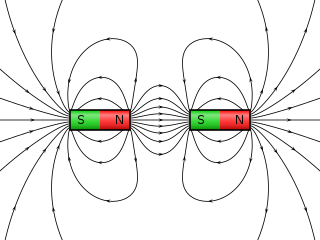
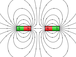
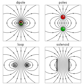
Magnetic fields for a bar magnet, and two bar magnets:
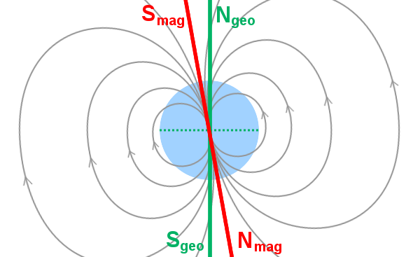
Geographic vs. magnetic North/South poles of the earth.
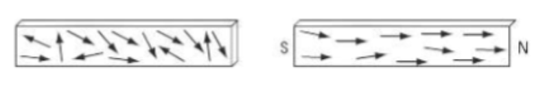
Domain Theory of Magnetism
Simply put, magnets are composed of smaller magnets known as magnetic domains, Each domain behaves as a smaller bar magnet. Normally, these domains are randomly scattered but int he presence of a magnetic field, the domains align; this causes the substance to become a temporary magnet.
Ferromagnetic materials behave magnetically when in a magnetic field. Therefore, if something is attracted to a magnet or affects a compass, all you know is that it is ferromagnetic. You do not know if the material is a permanent magnet. This explains the following phenomena:
- When a bar magnet is broken into two, the two smaller magnets are produced; a one poled magnet does not exist.
- Soft iron demagnetizes almost instantly while hard steel to alloys seem to ‘lock’ the aligned domains in position.
- Heating or dropping a magnet can cause it to lose its magnetism.
- A strong magnetic field opposite to a magnet can reverse the magnetism in a bar magnet.
- Stroking it in one direction with a strong magnet can magnetize a needle. This causes the needle’s domains to align.
Hand Rules
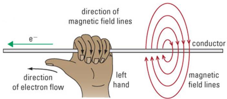
The third hand rule is shown later; with Forces:
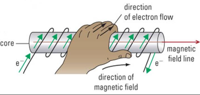
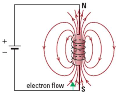
Solenoids
If the current is in a coil of conducting wire, the curled fingers of the left hand indicate the circular electron flow and the straight thumb indicates the direction of the straight magnetic field within the coil. The end of the solenoid that the thumb points to behaves like the north pole of a magnet. The other end behaves like a south pole. To strengthen the field and create an electromagnet an iron core could be placed in the centre of the solenoid as the domains of the iron align with the field strengthening the field. Note: If conventional current is used the same rules apply but using the right hand instead of left hand.
Adding fields together:
Current Electricity
Electric current is the rate at which a electrons flow through a conductor. The SI unit for current, I is in Amperes I. (For the following formula, q = charge, t =time and is an Alberta non-sense formula).
- Electrical circuits: Loops of moving electrical charge
- Conventional current: ‘the flow of positive charge’ through a circuit
- Electron Flow: the flow of negative charge, electrons, through a circuit.
Magnetic Force
The magnitude of the force acting on a current-carrying wire due to a magnetic field can be given by:
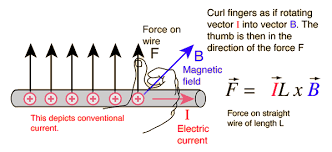
The equation may be multiplied by sinθ where θ is the angle between the direction of the field and the current. This can be ignored when θ=90 degrees because sin90 degrees equals to 1. Magnetic force on a moving charge The magnitude of the force acting on a moving charge due to a magnetic field can be given by
Where is the force acting on the wire, is the magnetic field, is the amount of charge, is the velocity of the charge, and is the angle between the direction of the field and the velocity.
Remember that the direction of the (conventional) current is the opposite to that of the flow of electrons.
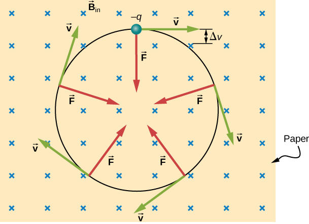
As the magnetic force is always perpendicular to the velocity of the charge, it acts as a centripetal force (see topic 6) and the charge follows a circular path. No work is done on the charge by the magnetic field.
Magnetic Forces on a Current Carrying Conductor
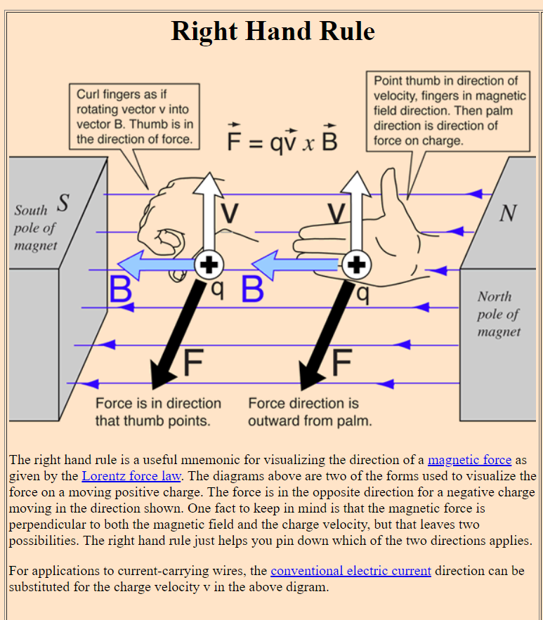
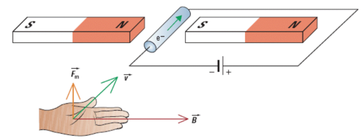
Third Hand Rule
Left hand’s thumb is the direction of negative charge flow (if flow of a proton, use right hand), v. The direction the magnetic field follows the tips of the left hand, B. Finally, the direction of magnetic force comes out of the left hand’s palm. **Often calculating an unknown using the following formula isn’t too difficult. In order to be awarded full marks, direction is critical ad a third dimension is introduced. In order to find said directions, the third hand rule MUST be used. (When given magnetic field strength, current, and or force)
**This formula only applies if l and B are perpendicular to each other. If they aren’t, then their components can be used.
**The SI unit of magnetic field strength is in Teslas, T = kg/(s*C)
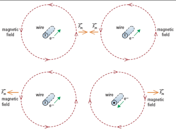
Magnetic Forces Between Two Current Carrying Conductors:
Currents in the same direction attract each other, and currents flowing in opposite directions repel each other. Additionally the convention to show that there is electron flow going away from the observer (into the page) is to use an x (tails of an arrow); inversely, to show that current is coming towards the observer, a dot is used (tip of an arrow).
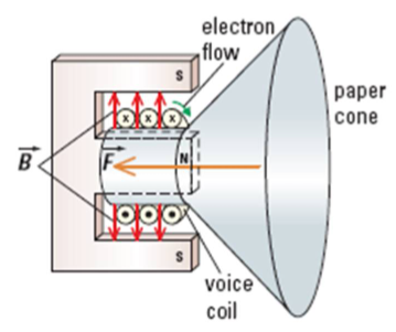
Application of Magnetic Forces
The rapid change of direction of electron flow, current causes the force acting on the cone to ungulate at the frequency of the switches. The magnetic coil acts like a solenoid, so when the direction of the current switches so do the ’poles’.
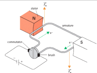
The current and the magnetic field (produced by the magnets (stators)) acting on the commutator produce a downwards and upwards force causing the motor to spin to 90 degrees. However to continue the spinning of the motor, the current is cut off, and the commutator is able to move past 90 degrees. After this point, there the current is applied again, and the force is again acting on the ‘edges’ of the commutator; causing it to spin.
Charged Particles in a Magnetic Field
In the formula, The force comes from the cumulative forces on the individual charges. Considering that a charged particle of charge q, is moving perpendicularly through a magnetic field, B the following deduction (formula) should be valid.
Using the third hand rule, (where current is ‘replaced’ by speed of a charged particle) the force acting on a particle will always be perpendicular to its motion. → This results in a kind of centripetal force acting on the particle as well as the magnetic force. In order to ‘shoot’ a particle undeviated in a magnetic field, the centripetal force must be equal to the magnetic force (in magnitude).
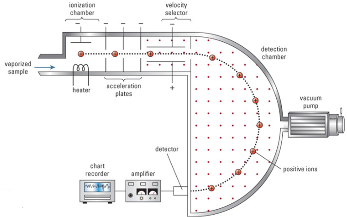
Mass Spectrometer
Ions are produced by providing energy into the system - heating or electrical discharge and then accelerated using voltage. The velocity of an accelerated particle can be determined using the following formulas/manipulations:
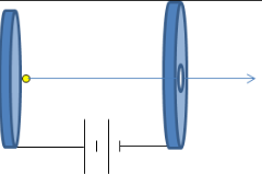
**If mass, charge and voltage are known, the velocity can easily be calculated. If not the formula above needs to be combined with other formulas.
After passing through the accelerating region, the ions then enter a velocity sector region (some problems don’t include this section). The velocity selector consists of perpendicular magnetic and electric field. Only charged particles of the correct charge and speed make it through the selector undeflected. When entering such plates, the following equality is valid:
After the velocity selector, the ions enter a perpendicular magnetic field and are deflected into a circular path. This is commonly known as the bending region. In this region, the centripetal force on the particle comes from the magnetic force on the moving charge in the magnetic field.
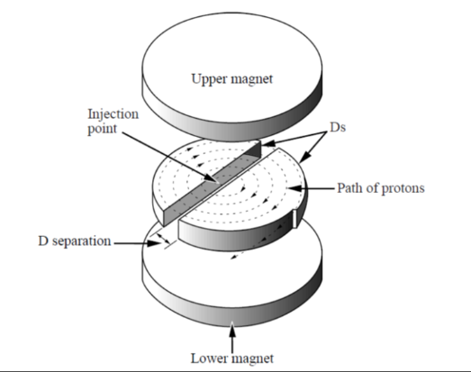
Cyclotron
A cyclotron is a particle accelerator that is constructed of two hollow metal shells shaped like Ds in a perpendicular magnetic field created by magnets, as shown below. The entire apparatus is placed in a vacuum. An alternating voltage is maintained across the D separation. Positively charged particles such as protons are injected near the centre of the Ds and travel in circular paths caused by the external perpendicular magnetic field. The frequency of the alternating voltage is adjusted to increase the speed of the particles each time they move across the Ds’ separation.
Auroras (Northern Lights)
Tremendous expulsions of magnetic energy from the solar atmosphere, called solar flares, expel streams of charged particles at speeds around 10% of the speed of light. When some of these particles strike Earth’s magnetic field, they are deflected by the magnetic force and spiral in a helical path along Earth’s magnetic field lines. These particles enter the atmosphere as they approach Earth’s magnetic poles, and collide with air molecules.
Component for velocity gets canceled out.
Faraday’s Law
Faraday’s law of induction (or simply Faraday’s law) is a basic law of electromagnetism predicting how a magnetic field will interact with an electric circuit to produce an electromotive force (emf)—a phenomenon known as electromagnetic induction. It is the fundamental operating principle of transformers, inductors, and many types of electric motors, generators and solenoids.[2][3]
The Maxwell–Faraday equation (listed as one of Maxwell’s equations) describes the fact that a spatially varying (and also possibly time-varying, depending on how a magnetic field varies in time) electric field always accompanies a time-varying magnetic field, while Faraday’s law states that there is emf (electromotive force, defined as electromagnetic work done on a unit charge when it has traveled one round of a conductive loop) on the conductive loop when the magnetic flux through the surface enclosed by the loop varies in time.
Faraday’s law had been discovered and one aspect of it (transformer emf) was formulated as the Maxwell–Faraday equation later. The equation of Faraday’s law can be derived by the Maxwell–Faraday equation (describing transformer emf) and the Lorentz force (describing motional emf). The integral form of the Maxwell–Faraday equation describes only the transformer emf, while the equation of Faraday’s law describes both the transformer emf and the motional emf
Electromagnetic induction
Magnetic field could cause electrons to move as a current
- Moving a wire through the jaws of a horseshoe magnet.
- Plunging a bar magnet into and out of the core of a coil
- Touching then removing a bar magnet to a core which was inside a coil of wire
Faraday’s Law of Electromagnetic Induction
Whenever the magnetic field in the region of a conductor is moving or changing in magnitude, electrons are induced to flow through the conductor.
Faraday’s Ring
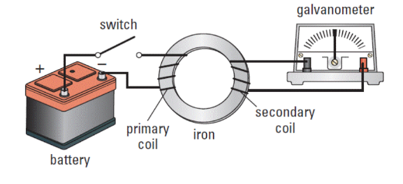
Before the switch is closed. Switch open therefore no current in the primary therefore no magnetic field therefore no change in field and no induction. When switch gets closed there is a surge in current in the primary therefore a changing flux therefore induced current in one direction in the secondary and in the galvanometer. While switch stays closed there IS current and magnetic flux in the primary however there is NO CHANGING flux therefore no induced current in the secondary. When the switch is opened the current stops in the primary. Domains scatter which is a change in flux which induces current in the secondary in the opposite direction.
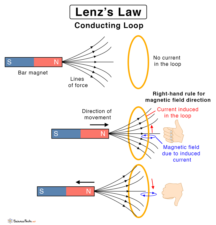
Direction of induced current/Lenz’s law
Lenz’s Law states that the direction of the induced current is such that the magnetic field resulting from the induced current opposes the change in flux that caused the induced current. ** consider Newton’s third law; or in English… Lenz’ law says that the direction of the induced current will oppose the change in flux that created it. It’s not a matter of increasing and decreasing, it’s a matter of direction.
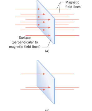
Flux
How to turn electricity into magnetism + inverse
Fuses
Fuses are placed in the main line of a parallel circuit. They are designed to melt and break a circuit if too much current goes through them. As loads are added to the circuit the current through the main line goes up. This current also goes through the fuse. The fuse is rated on how much current can pass through it before it melts and breaks the circuit. For Example, a 12 A fuse will allow up to 12 A of current to travel through the line. Any amount of current exceeding 12 A will cause the fuse to melt therefore breaking the circuit.
Switches
Switches. A switch can allow current through a circuit or a portion of a circuit. When a switch is opened no current flows through that line. A switch in the main line is an on off switch for the entire circuit. A switch in a parallel line is an on off switch for that line.