Circuits
Electromotive Force and Current
Within a battery, a chemical reaction occurs that transfers electrons from one terminal (leaving the battery positively charged) to another terminal (leaving negatively charged). Because of the positive and negative charges of the terminals, an electric potential difference exists between them. The maximum potential difference is the electromotive force, . If a battery were to have 12V labelled as its voltage, it would really represent its and is often higher than the actual voltage of the battery/power source.
For instance, common appliances are typically power rated; a power rating is the amount of power an appliance will dissipate under normal operation. E.g. a 100-Watt light bulb dissipated 100 Watts when wire in parallel across 120 volts (Standard household potential)
In a circuit, the battery creates an electric field within and parallel to the wire, directed from the positive end of the terminal to the negative end of the terminal. The electric field exerts a force on the free electrons inside the wire, and they respond by moving. This flow of charge is the electrical current, . Which is defined as the amount of charge per unit time that crosses an imaginary surface. (Can be thought of as a the amount of water crossing a cross section of a river per unit time) Electric current is the rate of flow of electrical charge through a conductive material; this is measured in Amperes, A (SI unit)
An electrical circuit is a closed loop of moving electrical charges. Whereas a conventional current is the flow of Positive charges through a circuit, an electron flow is the flow of negative charges through a circuit. [Default used/convention is conventional current] If the rate of flow is not constant the formula above gives the average current. If the current is a ‘direct current’, DC, (the same kind produced by batteries), then charge moves around the circuit in one direction at all times. If the current is an ‘alternating current’, AC, (the same kind produced by generators), then charges move one way then the opposite, in very quick succession. Ammeters measure the amount of electrical current. In order for ammeters to measure current correctly they should be in placed into the circuit such that current travels through the ammeter at the position where the current needs to be measured. [The ideal ammeter has 0 resistance] Voltmeters measure the electric potential difference between two points in a circuit. This means they need to be wired across 2 points in a circuit (typically across a power supply or a resistor (load)) [The ideal voltmeter has infinite resistance ]
Ohm’s law
The current that a battery can push through a wire is analogous to the water flow that a pump can push through a pipe. Greater pump pressures lend larger flows of water; similarly, greater battery voltages lend to larger electrical currents. . Additionally the rate at which water flows through a pipe is also affected by the length and diameter of the pipe. Longer and narrower pipes offer more resistance to the moving water, leading to smaller flowing rates. This translates to the electrical resistance of a wire. The electrical resistance of a wire is the ratio of . For many materials R remains constant over a wide range of voltages and currents. (Not true for light bulbs) Resistivity is measured in Ohms. The following equation illustrates this equivalency:
Materials that have a constant resistance for a wide range of voltages and currents are ohmic resistors, i.e. they obey ohms law. Likewise, materials that have changing resistance over a range of voltages and currents are called non-ohmic resistors, as they don’t obey ohms law. For a wide range of materials, the resistance of a piece of material is directly proportional to the length, L and inversely proportional to the cross sectional area, A. Ohm’s law is not a fundamental law of nature (like newton’s laws of gravitation, or the other 3). It is only a statement that describes how electric circuits behave. Based on the extent that a wire offers resistance to the flow of charges, it can be called a resistor. Unless labelled, wires are assumed to have no resistance. They are generally used to limit the amount of current and establish proper voltage levels.
Resistance and Resistivity
In a water pipe, the length and cross sectional area of the pipe determine the resistance that the pipe offers to the flow of water. Additionally for the equation listed below, is the proportionality constant known as the resistivity of the material; this is where the analogy falls apart, as based on the material of the wire, the resistivity is going to change based off of its chemical structure. This translates to the resistance of the wire, with the aforementioned variables to the following formula:
Additionally, when other formulas can be combined to create proportionalities such as:
The resistivity of a material also depends on its temperature. Where are the resistivities of respectively. The term is the temperature coefficient of resistivity; it is positive for conductors, negative for insulators. When the first equation is multiplied by , the second equation is found.
Electric Power
One of the most important functions of the current in an electric circuit is to transfer energy from a source (such as a battery or a generator) to an electrical device. When an amount of positive charge, , moves from the higher potential to the lower potential terminal, its electrical potential decreases. As the change in energy per unit time is the power, , the electric power associated with this change can be expressed through the following equation (SI unit in Watts, W):
The last formula is used only when the power is dissipated by a resistor with a potential difference of V across it.
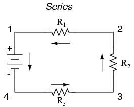
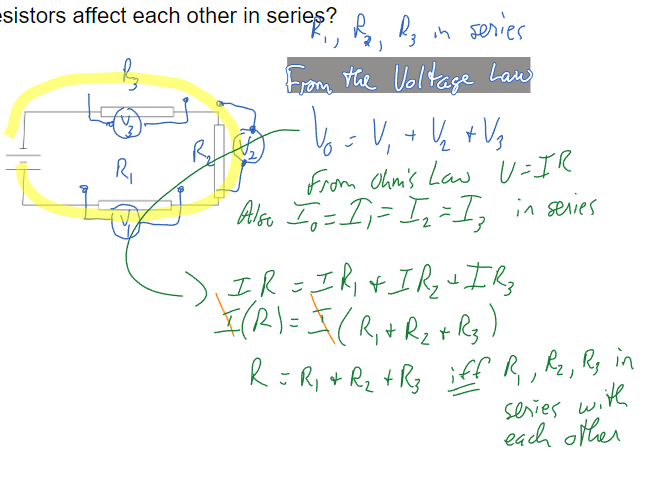
Series Wiring
Series that contain several devices and are wired such that the same amount of electric current goes through every device. In general the voltage across all the resistors in series is the sum of the individual voltages across each resistor. A series circuit is one in which all power supplies and loads are in a single path, meaning that all current goes through each load. (In series = all elements are successive)
When resistors are in series, the sum of all resistors is the resistance for the whole system; This only applies to devices in series; devices in parallel use a different formula.
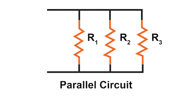
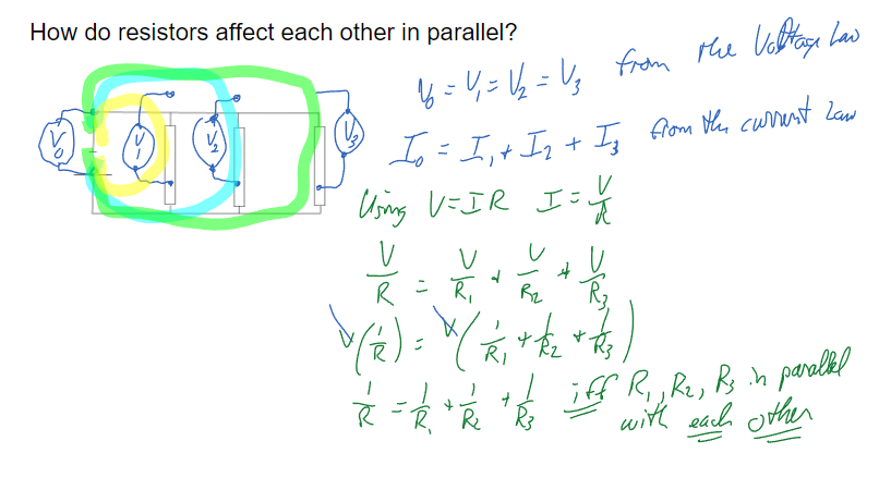
Parallel Wiring
A parallel circuit is one in which each power supply and load is wired to a separate path in the circuit. Such that there is equal voltage distributed across all devices.
When two resistors, and are configurated in a parallel circuit, each receives current from the power supply as if the other resistor wasn’t present. According to the definition of resistance, , a larger current implies smaller resistance. Thus the two parallel resistors behave as a single equivalent resistance that is smaller than either or . (The cross sectional area of allows for more current to flow than two separate currents would)
As in a series circuit, it is possible to replace a parallel combination of resistors with an equivalent resistor that results in the same total current and power for a given voltage as the original combination. To determine the equivalent resistance for the two resistors use the following formula (derivation first):
Where is the equivalent resistance. Hence when two resistors are connected in parallel, the following statement can be made: The total current from the voltage source is the sum of the currents in the individual resistors.
In general, the power delivered to any number of resistors in parallel is equal to the power delivered to the equivalent resistor (which allows for replacement).
Combinational; Complex Wiring
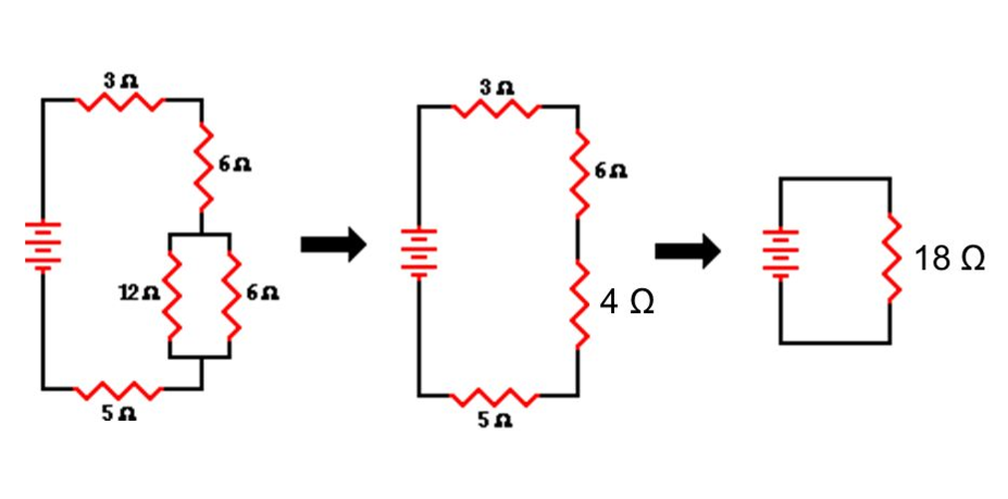 In order to solve these kinds of problems, simplify the circuit until all parallel portions can be ‘simplified’ into a circuit entirely in series.
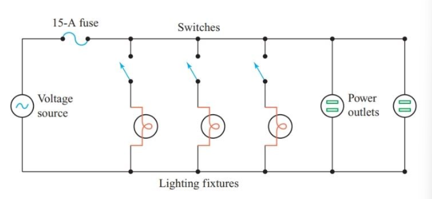
Fuses
Fuses are placed in the main line of a parallel circuit. They are designed to burn and melt if too much current goes through them; these are often used to ensure that things don’t burn out.
Why wire things in series?
To split the voltage. This is often called a voltage divider. Batteries tend to come in standard voltages that may end up being too large for the circuitry you are operating. Putting a resistor in parallel with your circuitry splits the voltage by having the added resistor take a portion of the voltage.
Why wire things in parallel? This is the standard for most circuits. Wiring things in parallel allows for the greatest power to be used in the circuit. Each parallel line can be separately controlled by switches without affecting the other parallel lines giving more control. Switches in a series circuit or the main line of a parallel circuit shut off power to everything.
Internal Resistance
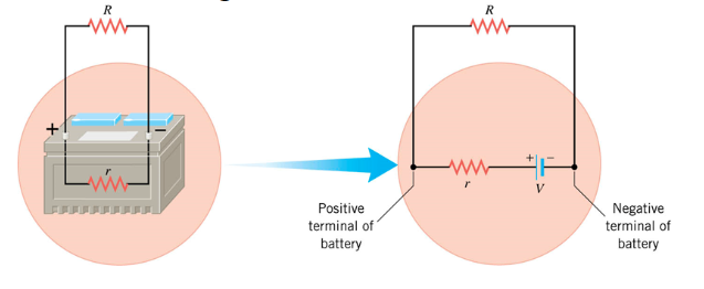
Batteries and generators add some resistance to a circuit; this is internal resistance (terminal voltage). As mentioned earlier, every power source has at least a little resistance and this is illustrated the diagram below.
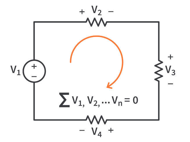
Kirchhoff’s Voltage Law; Loop Law
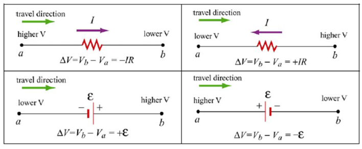
Around any complete path through an electrical circuit, the sum of the increases in electrical potential (from batteries, generators etc.) is equal to the sum of the decreases in electrical potential (through various resistances loads); Net voltage,
The energy lost to the resistor in a circuit are equal to the voltage of the battery
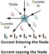
Kirchhoff’s Current Law
At any junction point in an electrical circuit, the total current into the junction is equal to the total electrical output of the junction. ** Both relate to the law of conservation of charge and energy for an isolated system.
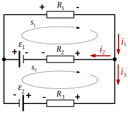
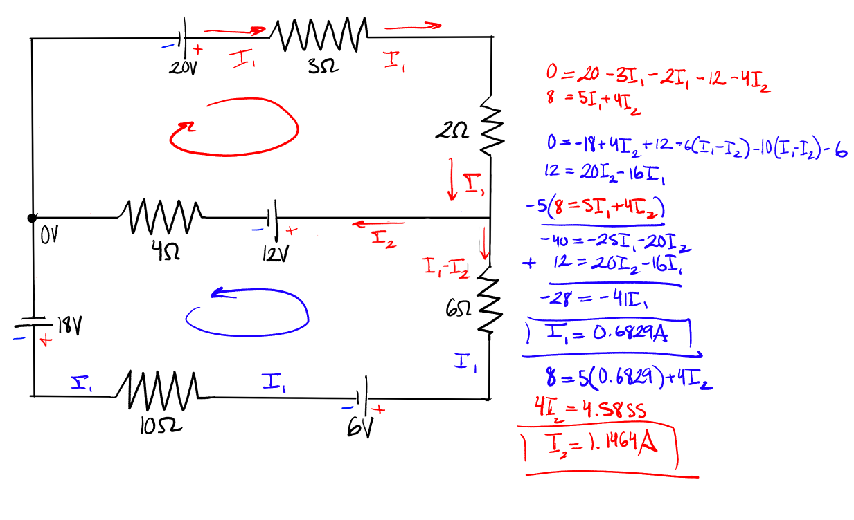
Multiloop Circuits
In situations where there are more than one power supply, Kirchhoff’s laws need to be applied. Identify a direction for the possible loops that may arise. If chosen incorrectly, it will show up in work. (Current will be negative; in the opposite direction)
It is recommended to chose the outer loop or the loop with the most voltage.
Potential Dividers
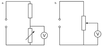
A potential divider is a circuit that uses resistors to supply a variable voltage to a device. They are used to dim lights, adjust temperature, audio etc.
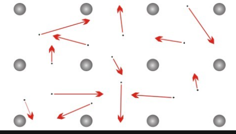
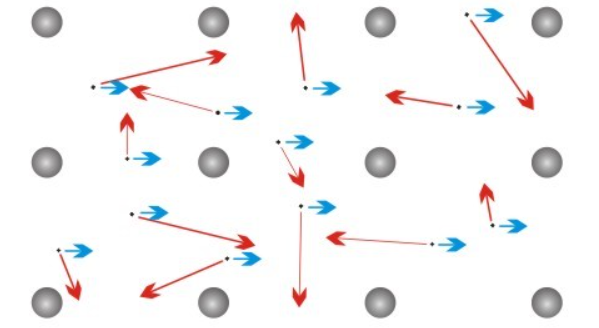
Drift Velocity
A solid piece of metal, APT consists of metal ions, arranged in a particular pattern, a crystal lattice. The electrons in the meatal are freely moving between the ions. The motion of the free electrons is random ‘Brownian motion’ We say they have random thermal motion with an average speed which increases with temperature.
If a potential difference is applied between two points in the conductor, an electric field is produced. As a consequence, an electric force will act on the charge carriers then another motion is added to the random thermal motion. Additionally the charge carriers will drift along the conductor and a steady charge will flow through the conductor.
- This results in a drift velocity.
The value of the drift speed is usually very small, in everyday situations, Additionally, the electric current arising from the movement of a given number of charge carriers through a conductor uses the following formula:
Where = number of charge carriers per unit volume i.e. charge density (), = cross sectional area of the conductive material (), = average drift speed of charge carriers (), = charge of the carriers
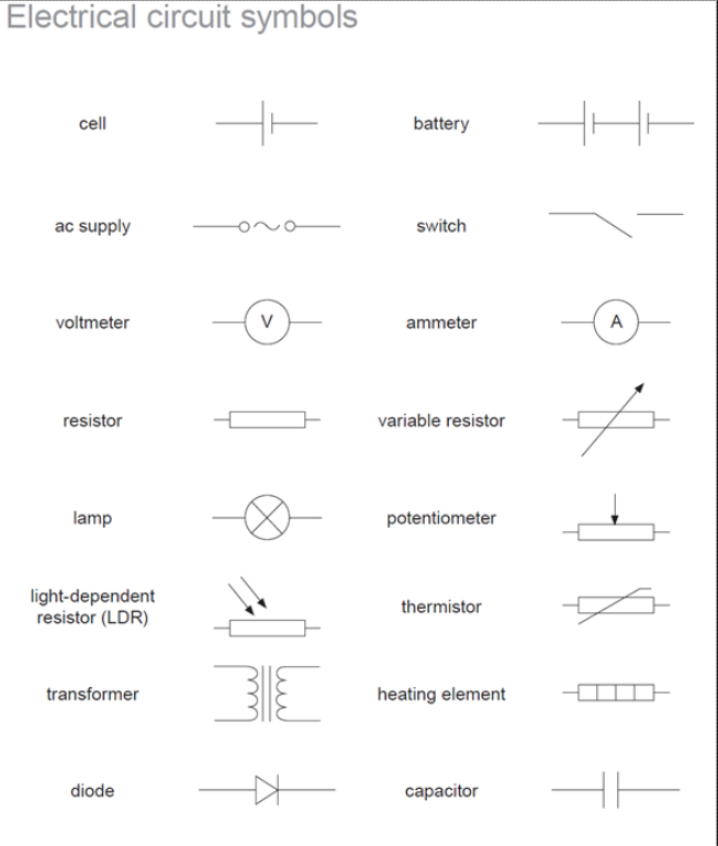
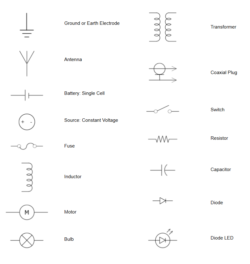
Drawing Circuits